ICS-DUAL / Static leveling

Industrial Dual-Axis & Single-Axis Inclinometer Sensors

Specify gravity-referenced inclination measurement for solar tracking, stationary platforms and machine leveling. Match the mounting orientation before selecting the angle range.

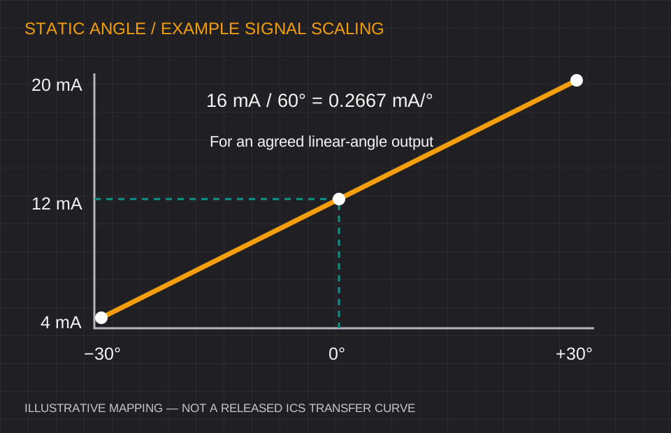
Illustrative linear mapping from minus 30 to plus 30 degrees onto a 4 to 20 milliamp signal
Illustrative scaling example, not a released ICS transfer curve. Open diagram ↗

Define your operating window

ICS-DUAL: range, interface and error budget.

Axes & range
Dual-axis X/Y ±5°, ±10°, ±15°, ±30°, ±45°, ±60°, ±90°; single-axis vertical 0–360°
Performance request
Static accuracy target ±0.05° to ±0.1°; confirm range and temperature conditions.
Output interface
Dual-channel 4–20 mA, 0–5 V, 0–10 V, RS485 Modbus RTU or CANopen
Installation environment
Request IP67 / IP68 configuration, enclosure material and −40°C to +85°C qualification.

Values are selection targets for quotation. Model-specific test conditions, calibration and released specifications govern acceptance.

Where this configuration fits

Solar tracker single-axis tilt control, scissor-lift platform leveling, machine beds and marine platforms.

Before approving the sample

  • State whether the sensor mounts horizontally or vertically.
  • Specify static accuracy across your actual range, supply and temperature.
  • For two analog axes, verify two input channels and the channel scaling.

Comparing an existing inclinometer?

Reference families: POSITAL TILTIX ACS, SICK TMM88 / TMS22, Pepperl+Fuchs F99 and Rieker. These are evaluation starting points. Confirm exact model, mechanical drawing, electrical behavior and acceptance test before claiming interchangeability.

Review the replacement checklist →

ICS-DUAL / Installation & integration decisions

One angle range. A defined analog or digital handoff.

A solar tracker, stationary platform and machine bed may all need tilt feedback, but their electrical and installation requirements differ. Define the mounting face and required signal first, then review the model-specific range and error limits.

Inclinometer analog output: define both endpoints

For an illustrative linear ±30° angle mapping onto 4–20 mA, zero is 12 mA and sensitivity is 16 mA / 60° = 0.2667 mA per degree. The PLC must use the same endpoint definition. A force-balanced instrument may instead specify a sine-related transfer function, so use the selected model’s definition.

  • Two analog axes need two input channels and an agreed X/Y sign convention.
  • Confirm supply, permissible load, signal reference and diagnostic current levels.
  • Record whether the signal is angle-linear, gravity-component-related or otherwise conditioned.

Inclinometer digital output: request the actual map

RS485 is an electrical interface; Modbus RTU describes a communication method. The register locations, signed values, scaling and byte order still belong to the specific firmware. CANopen integration similarly needs the EDS and supported objects.

  • Agree baud rate, device address and the requested update period.
  • Verify units, register width, byte/word order and fault values in the PLC.
  • Request zero-set, filter, parameter-retention and factory-reset instructions.

Solar tracker rows: installation and temperature

For a solar tracker OEM program, describe the rotation reference, end-of-travel and stow angles, daily temperature window and field cable layout. Define accuracy across those conditions rather than choosing by display resolution alone.

  • Select vertical single-axis rotation or the actual dual-axis mounting arrangement.
  • Separate room-temperature accuracy from full operating-temperature error.
  • Include required node addresses, harness lengths and quantity schedule in the OEM brief.

Example only: ±30° mapped linearly to 4–20 mA

AngleExample signalPLC interpretation
−30°4 mALower endpoint
0°12 mADefined installation zero
+30°20 mAUpper endpoint
Can I use a dual-axis sensor as two independent current signals?

Request the exact output configuration and confirm that both axes are provided as independent channels. Verify pinout, supply and PLC loading for that model.

Will a new sensor replace a discontinued board-level chip directly?

A board-level chip and an enclosed industrial transducer have different power, mechanical and signal interfaces. Send the old module drawing and circuit-level requirements for a system review.

ICS-DUAL / Engineering integration package

Request the files your design review needs.

Choose the document and send your range, interface and mounting requirements. We review the matched configuration and confirm which released files can be supplied.

Static MEMS or gyro-compensated dynamic?

Match the motion before the resolution.

Static or slow-moving equipment

Start with ICS-DUAL for solar trackers, platform leveling and stationary machinery. For micro-tilt monitoring, review ICS-PREC or ICS-GEO and the temperature error budget.

Acceleration, vibration or sudden stops

Review ICS-DYN for moving excavator booms, loader buckets and vehicles. Sensor fusion reduces apparent tilt from motion; validate dynamic error, bandwidth and recovery against your duty cycle.

Inclinometer vs. accelerometer: understand the difference →

Replacing an existing unit? Start with the interface checklist →

Planning 20+, 100+ or 1,000+ units? Solar trackers, scissor lifts & construction equipment OEM.Request volume pricing & OEM interface settings ↗

ICS-DUAL / project inputs

Configure your ICS-DUAL inquiry and integration scope.

Send the installation requirements below. Request 3D CAD, pinout and the calibration scope for the configuration under review.

Industrial sensor inquiry form

For acceleration and vibration during measurement, review ICS-DYN. Solar tracker preconfiguration can be scoped with the OEM request.

Range, environment & mounting (optional)

Describe the required conditions. These values are your application targets, not a confirmed product specification.

Engineering documents & project package (optional)
Files requested for configuration review

Package scope and document availability are confirmed for the matched configuration. A package request has no separate price; select the display accessory once if it is needed.

Installation accessories (optional)

Selected accessory planning allowance: USD 207. Indicative add-ons; the formal quote confirms compatibility, quantity, freight, tax and lead time.

Your request goes to [email protected]. CAD, performance and delivery are reviewed after feasibility checks for the requested configuration.