
TiltCore / engineering resources
Inclinometer vs. Accelerometer: Working Principle & Calibration
An accelerometer reports specific force; an inclinometer reports an angle relative to a defined reference. The first selection question is whether gravity dominates the measurement or whether machine acceleration must also be considered.
MEMS, sensor fusion, electrolytic or force-balanced?
Choose the measurement method before choosing the smallest display increment. These are technology classes; the exact sensing element, range and performance of an ICS configuration must be established by its released datasheet.
| Method | How tilt is estimated | Useful starting context | What to verify |
|---|---|---|---|
| Static MEMS | A calibrated gravity projection is converted to angle. | Stationary platforms and slow solar tracking | Offset, gain, cross-axis effects, temperature and settling after motion |
| Accelerometer + gyroscope fusion | Angular-rate history and gravity information are combined. | Excavators, loaders and moving platforms | Motion profile, latency, gyro bias, saturation and recovery |
| Electrolytic tilt sensing | A conductive liquid redistributes relative to electrodes. | Slow, stable structural or geotechnical measurements | Thermal stability, settling, excitation electronics and movement during measurement |
| Force-balanced servo | A feedback loop applies restoring torque to a sensing mass. | Precision reference and industrial inertial measurements | Transfer function, supply, bandwidth, mounting and temperature terms |
Method references: Analog Devices AN-1057, Jewell sensor selection and force-balance principles. None is an ICS qualification report.
When acceleration looks like a change in angle.
For an agreed two-dimensional axis convention at rest, θ = atan2(a_x, a_z). A possible three-dimensional pitch convention uses atan2(−a_x, √(a_y² + a_z²)). Signs and axis definitions depend on the installed frame. A single accelerometer axis using an inverse-sine conversion also loses angular sensitivity near its ±90° positions.
In a simple level example with 1 g vertical gravity and 0.1 g horizontal acceleration, atan(0.1) ≈ 5.71°. The result is an apparent tilt even though the mount has not rotated. A low-pass filter can suppress some vibration but also changes settling time; it cannot identify every sustained acceleration as separate from gravity. AN-1057 explains these assumptions.
Gyroscopes add short-term rotation information. Fusion can improve performance during motion, but prolonged acceleration, bias drift, vibration, saturation and tuning still matter. A six-axis IMU alone does not provide an independent, drift-free absolute heading. Compare the static output guide with the dynamic integration guide using the same duty cycle. POSITAL explains static and dynamic sensing approaches.
Resolution, repeatability and absolute accuracy answer different questions.
- Resolution: the smallest reported increment. 0.001° = 3.6 arcseconds; 0.0005° = 1.8 arcseconds.
- Repeatability: the spread when returning to the same condition; state mounting, temperature and bandwidth.
- Absolute error: difference from the reference angle across the specified range and conditions.
- Thermal drift: zero and sensitivity changes with temperature, including gradients and warm-up.
A fine output increment cannot remove a biased datum or a temperature-dependent scale error. Ask whether an accuracy limit is typical or maximum, whether it includes thermal terms, and which angle, axis and bandwidth it covers. Do not add separately listed terms until the datasheet makes clear what is already included.
Digital inclinometer calibration: factory characterization versus field zero.
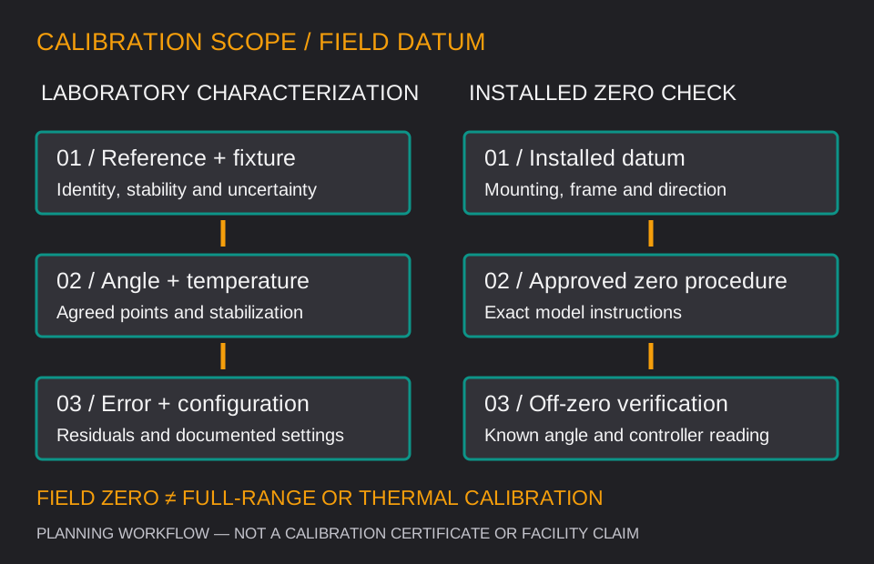
Define the factory or laboratory calibration scope.
- Identify the exact serial number, hardware and firmware revision. Establish the reference instrument, its calibration status and uncertainty.
- Agree the fixture, reference face, mounting torque and axis transformations. Follow the device-specific warm-up and stabilization instructions.
- Select zero, positive and negative reference angles over the required range. Include repeated approaches if hysteresis or repeatability matters.
- For thermal characterization, agree temperature points and stabilization criteria. Record both zero and sensitivity behavior; a chamber setpoint alone does not establish sensor equilibrium.
- Record raw and corrected results, output scaling, bandwidth and configuration. Any compensation write or firmware command must follow the exact model instructions.
- Review the residual errors and uncertainty against the agreed acceptance rule. Retain the configuration and report revision with the supplied unit.
Establish and check the installed field zero.
- Place the machine or structure in its agreed reference condition. Confirm that the reference itself is stable and sufficiently accurate for the task.
- Secure the mounting face and cable strain relief. A three-point adjustment plate may help establish alignment, subject to fixture stiffness and compatibility.
- Verify power, actual connector pinout, interface and X/Y direction. Record the old zero and configuration before changing settings.
- Set zero only using the approved model procedure. Do not reuse a different manufacturer's teach-input timing or write an assumed register.
- Check one or more known off-zero positions and return to datum. Confirm sign, scaling, repeatability and the downstream controller reading.
- Record date, operator, reference, temperature and resulting settings. Investigate drift or mechanical movement before repeatedly applying new offsets.
A field zero adjustment corrects the installed offset at that condition. It does not by itself establish full-range gain, temperature compensation, uncertainty or dynamic accuracy. For traceability, request the documented calibration chain and uncertainty; a logo or the phrase “NIST traceable” alone is insufficient. NIST describes metrological traceability.
Why zero-setting cannot remove a scale error.
Consider the illustrative equation θ_read = 1.002 × θ_reference + 0.04°. Subtracting the 0.04° offset leaves a 0.06° error at +30°. This arithmetic example is not a sensor measurement or an ICS test result; it shows why both offset and gain need evaluation.
Agree the installed acceptance check before ordering samples.
State the application tolerance and measurement conditions in the sample request. Define who supplies the reference, how uncertainty is considered, how long the reading must settle and which result releases the design. A prototype evaluation should cover the sensor, fixture, wiring, controller conversion and saved configuration together.
- Static: zero, positive/negative angles, return-to-zero, cross-axis influence and the required thermal window.
- Dynamic: repeatable start/stop and vibration conditions, maximum allowed error, latency and recovery time.
- Networked: node address, timing, message or register scaling, startup, data timeout and communication loss.
- Display/alarm: known angles, units, thresholds, hysteresis, delay and defined fault states, with machine safety assessed separately.
Convert tilt to displacement only after defining the geometry.
Slope in mm/m = 1,000 × tan(θ); 0.005° is approximately 0.0873 mm/m. For a rigid beam with physical length L, its end-height component is L × sin(θ). Using horizontal projected distance instead gives the tangent relationship. Segment accumulation, initial geometry, mounting changes and reference stability must be included before interpreting tilt as settlement. See horizontal and vertical monitoring methods.
Questions that change the calibration brief.
Can a USB adapter calibrate any inclinometer?
No. The adapter must match the electrical interface, isolation, software and approved device commands. It is a communication tool, not an angle reference. Ask about the configuration and wiring package for the exact model.
Does a high-resolution sensor always require a precision leveling base?
Specify the mechanical datum and allowable mounting error first. The standard adjustment plate is an accessory request, not a certified precision fixture. Ask for stiffness, adjustment range and the approved drawing when the error budget depends on it.
Is a factory report the same as accredited calibration?
No. Request the issuer, scope, method, reference chain and uncertainty, and any accreditation scope your procurement specification requires. Availability and terms must be confirmed for the supplied model.