ICS-DYN / Moving machinery

Gyro-Compensated Dynamic Inclinometers for Mobile Machinery

Reduce motion-induced apparent tilt with a six-axis accelerometer and gyroscope fusion architecture. Define vibration, acceleration and response time using the actual machine duty cycle.

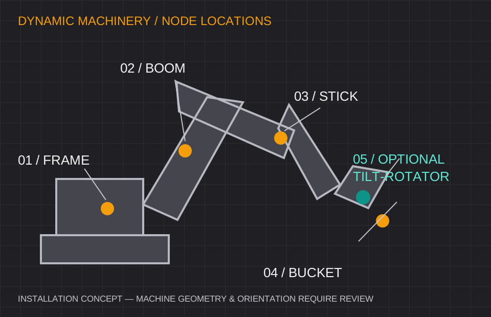
Conceptual excavator with sensor locations on the frame, boom, stick, bucket and optional tilt rotator
Installation concept; linkage dimensions, node count and sensor orientations are machine-specific. Open diagram ↗

Define your operating window

ICS-DYN: range, interface and error budget.

Axes & range
Dual-axis pitch / roll targets up to ±90°; single-axis vertical requests require configuration review. Heading requires a separate reference and agreed drift limits.
Performance request
Dynamic accuracy target ±0.1° to ±0.2° under an agreed test profile; fusion does not guarantee immunity to every acceleration.
Output interface
SAE J1939, CANopen, RS485 or 4–20 mA — configuration-specific
Installation environment
Specify shock, vibration spectrum, mounting stiffness and operating temperature.

Values are selection targets for quotation. Model-specific test conditions, calibration and released specifications govern acceptance.

Where this configuration fits

Loader bucket inclinometer sensors, excavator guidance, fire ladders, agricultural machinery and mobile cranes.

Before approving the sample

  • Provide acceleration magnitude / duration and vibration spectrum.
  • Confirm J1939 PGNs or CANopen object dictionary, baud rate and update rate.
  • Validate installed-system latency, transient error and recovery after motion.

Comparing an existing inclinometer?

Reference families: POSITAL Dynamic TILTIX, SICK dynamic inclinometers and comparable mobile-machine tilt sensors. These are evaluation starting points. Confirm exact model, mechanical drawing, electrical behavior and acceptance test before claiming interchangeability.

Review the replacement checklist →

ICS-DYN / Installation & integration decisions

Loader bucket inclinometer sensors as a coordinated machine request.

Start with the machine and measurement task. A dynamic sensor at the bucket does not by itself define tooth-tip position: a guidance system also needs linkage geometry, mounting references, synchronization and a validated controller model.

Four nodes or five: describe the linkage

A useful discussion starts with frame attitude plus boom, stick and bucket measurements. A fifth location may be needed for a tilt-rotator or another moving joint. The controller architecture determines which angles must be measured and how they are synchronized.

  • Record the reference direction and mounting orientation at every location.
  • Supply linkage drawings, attachment changes and permitted mounting envelopes.
  • Include the harness, power distribution and junction box in the request.

Acceleration profile before dynamic accuracy

A gyroscope measures angular rate while an accelerometer supplies a gravity-related reference. Fusion can improve attitude estimation during motion, but sustained acceleration, bias, vibration and saturation still matter. Mechanical shock survival and measurement accuracy during a shock are separate specifications.

  • Provide acceleration magnitude and duration, angular rates and vibration spectrum.
  • Agree sample/update rate, total output latency and post-motion recovery.
  • Use an installed-machine acceptance profile instead of assuming static accuracy applies in motion.

J1939 and CANopen: send the integration target

State the required network interface explicitly. A J1939 request should define the expected PGNs/SPNs, scaling and timing; a CANopen request should define the device profile, objects and PDO behavior. Connector shape alone does not establish wiring or protocol compatibility.

  • Request PGN/DBC material or the CANopen EDS as appropriate.
  • Define node addresses, bus speed, bus termination and diagnostics.
  • Confirm M12 or Deutsch connector coding and the model-specific pinout.

Excavator sensor-location brief

LocationWhat to definePackage scope
FrameMachine roll/pitch reference and mounting faceBase node
BoomJoint reference, range and mounting envelopeBase node
StickRelative angle, linkage geometry and cable travelBase node
BucketAttachment zero, working range and shock profileBase node
Tilt-rotatorExtra joint motion and controller mappingOptional fifth node
Does a five-node request include a complete guidance controller?

It defines the requested sensing locations for review. Specify the controller, linkage model, synchronization, harness and acceptance scope separately in the project brief.

Which package should I request for a tilt-rotator?

Use the five-node concept as a starting brief and describe every measured joint. The final number and orientation depend on the installed machine architecture.

ICS-DYN / Engineering integration package

Request the files your design review needs.

Choose the document and send your range, interface and mounting requirements. We review the matched configuration and confirm which released files can be supplied.

Static MEMS or gyro-compensated dynamic?

Match the motion before the resolution.

Static or slow-moving equipment

Start with ICS-DUAL for solar trackers, platform leveling and stationary machinery. For micro-tilt monitoring, review ICS-PREC or ICS-GEO and the temperature error budget.

Acceleration, vibration or sudden stops

Review ICS-DYN for moving excavator booms, loader buckets and vehicles. Sensor fusion reduces apparent tilt from motion; validate dynamic error, bandwidth and recovery against your duty cycle.

Inclinometer vs. accelerometer: understand the difference →

Replacing an existing unit? Start with the interface checklist →

Planning 20+, 100+ or 1,000+ units? Solar trackers, scissor lifts & construction equipment OEM.Request volume pricing & OEM interface settings ↗

ICS-DYN / project inputs

Configure your ICS-DYN inquiry and integration scope.

Send the installation requirements below. Request 3D CAD, pinout and the calibration scope for the configuration under review.

Industrial sensor inquiry form

State the acceleration profile and required response time. A four- or five-node package request defines integration scope, not installed-system accuracy.

Range, environment & mounting (optional)

Describe the required conditions. These values are your application targets, not a confirmed product specification.

Engineering documents & project package (optional)
Files requested for configuration review

Package scope and document availability are confirmed for the matched configuration. A package request has no separate price; select the display accessory once if it is needed.

Installation accessories (optional)

Selected accessory planning allowance: USD 207. Indicative add-ons; the formal quote confirms compatibility, quantity, freight, tax and lead time.

Your request goes to [email protected]. CAD, performance and delivery are reviewed after feasibility checks for the requested configuration.