
ICS / Application engineering briefs
Inclinometer applications start with the installed reference.
Choose the measurement duty, then define the mounting, interface and acceptance conditions. Use these six briefs to prepare an actionable OEM inquiry.
Six starting contexts
Which motion and reference must the sensor resolve?
The linked ICS families are inquiry starting points. Released model specifications and machine or monitoring design determine the final selection. These are planning briefs, not completed customer installations.
01 / ICS-DYN review
Excavator and loader bucket angle feedback
Separate the angle of each moving link from the machine geometry used to calculate the tool position.
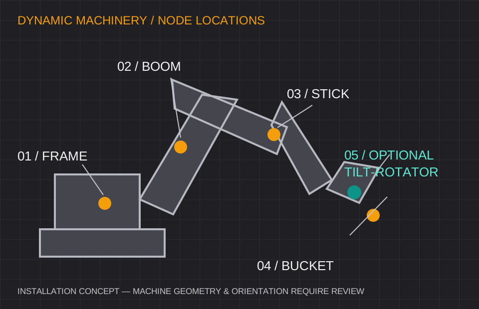
A frame, boom, stick and bucket concept uses four measurement locations; a tilt-rotator may add another tilt input. Rotary azimuth needs a separate reference when the application requires it. Agree whether the controller needs absolute angles in a common frame or relative joint angles. Sensor placement, axis transforms, pivot dimensions and bucket geometry all enter a machine guidance calculation. A tilt sensor alone does not establish a surveyed 2D or 3D tool position.
Define representative starts, stops, travel, digging impacts and simultaneous link movement. Agree angle-error, latency and recovery limits with the machine integrator rather than transferring a static accuracy figure into a moving-machine claim.
Bring these inputs to the design review.
- Sensor locations and four/five-node scope
- J1939 PGNs or CANopen objects, addresses and timing
- Harness routing, connector choice and machine acceptance profile
02 / ICS-DUAL review
Solar tracker position and stow reference
Define the rotation reference and the required angle at each controller state, including stow.
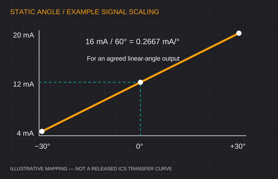
For a slowly rotating tracker, begin with the installed axis and mounting orientation. A vertical single-axis rotation and a horizontal pitch/roll installation use different reference conventions. The controller must interpret the same sign, zero and range as the sensor. Specify the operational and stow windows, temperature exposure, supply at the far end of the row and the behavior when position data is lost.
For OEM rows, agree node addressing, baud rate, cable length, configuration retention and a repeatable installation zero check. A sample program should test the actual row geometry and thermal conditions before ordering repeated configurations in volume.
Bring these inputs to the design review.
- Axis convention, working range and stow angles
- Analog scaling or Modbus map and data timeout
- Row quantities, supply/cable budget and thermal acceptance
03 / ICS-GEO review
Horizontal beams and vertical borehole arrays
Establish the monitoring geometry and stable reference before converting a tilt trend into displacement.
A horizontal beam relates angle to an agreed beam length and datum; a vertical in-place array resolves segment inclination along the installation. These are different geometries. Document segment spacing, azimuth or axis orientation, initial readings and how the reference is maintained. Temperature, mounting movement and cumulative measurement error can all appear as structural movement if they are omitted from the model.
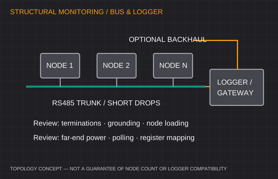
Review logger register handling, polling time, cable voltage drop, grounding and protection for the complete network. The allowable number of nodes is a design result from the actual devices and wiring, not a universal property of an RS485 label. Radio compatibility must be confirmed for the chosen gateway and deployment location.
Bring these inputs to the design review.
- Beam length or vertical segment spacing and reference
- Logger, node count, sampling interval and power budget
- Sealing, service access and trend/alert interpretation
04 / ICS-DUAL review
Aerial platform and scissor-lift leveling
Separate stationary setup indication from angle measurement while the machine is moving.
For stationary or slow leveling, define chassis pitch and roll relative to the required setup plane. Consider mounting flex, the readout location and the angle seen by the operator. If the control loop must measure during travel, abrupt starts or significant vibration, review the dynamic family and a representative motion profile instead of relying on a heavily filtered static measurement.
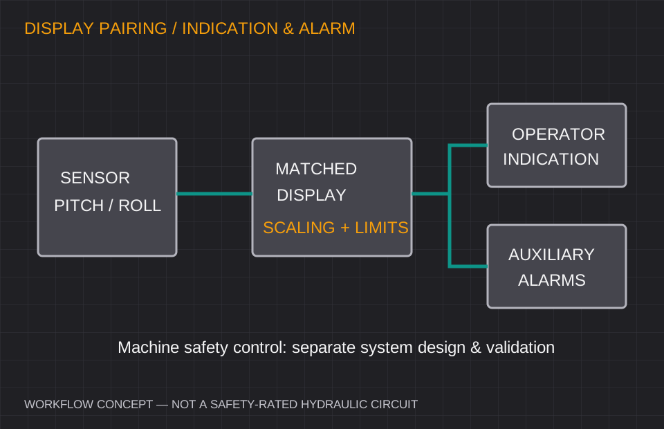
A display alarm and two relay contacts do not by themselves establish a certified anti-rollover function. The machine designer must define sensor faults, lost communication, power loss, alarm reset and the behavior of the relevant control system. The sample review should include the complete sensor/readout/controller chain.
Bring these inputs to the design review.
- Stationary leveling or moving-machine measurement
- Pitch/roll limits, display units and alarm behavior
- Mounting stiffness, fault handling and machine validation
05 / ICS-DYN review
Marine platform roll and pitch measurement
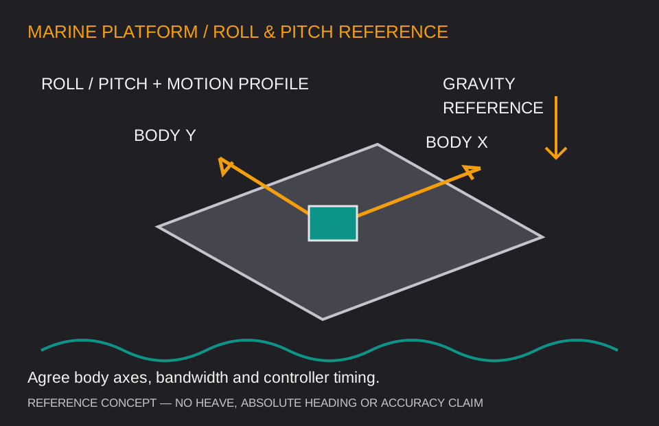
Define the platform frame and the motion bandwidth separately from environmental survival.
Describe the expected roll, pitch, acceleration and vibration, along with the controller interface and the location of the sensor relative to the vessel frame. Gravity-referenced inclination does not independently supply absolute heading or heave. Long-period acceleration and gyro bias remain part of the system evaluation even when a fused sensor is selected.
An enclosure IP rating does not establish resistance to every salt, chemical, galvanic or cable-entry exposure. Review housing and fastener materials, connector sealing, cable strain relief and supply transients for the actual installation. Agree the operating reference and motion test before comparing readings from devices using different filter bandwidths.
Bring these inputs to the design review.
- Vessel/platform reference frame and required bandwidth
- Controller protocol, supply transients and timing
- Salt exposure, mounting materials and cable sealing
06 / ICS-PREC review
Wind-tower, antenna and precision alignment
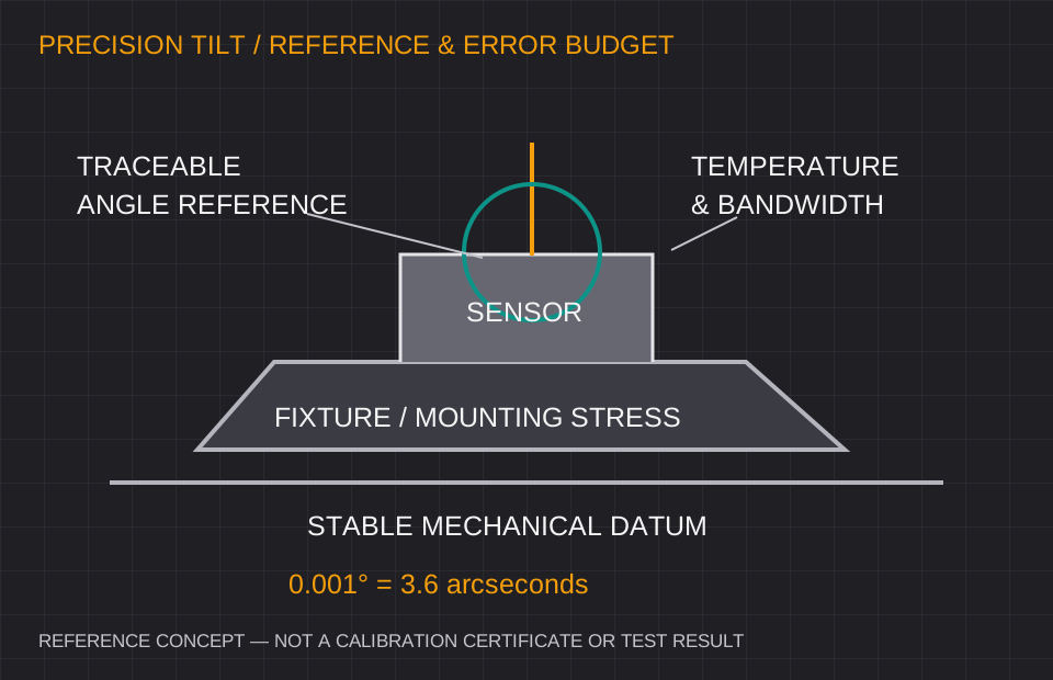
Allocate mounting, reference and temperature errors before selecting a resolution target.
A small reported angle step is useful only when the fixture, reference and sensor stability support the measurement. Define whether the project needs absolute leveling, repeatable relative movement or a long-term trend. For wind towers and mounted antennas, document the measurement location, structural flex and baseline condition. Inclination does not provide independent north finding.
Request the full error definition, thermal conditions, bandwidth, warm-up and calibration uncertainty. Separate a general adjustment plate from a precision reference fixture; the nominal accessory price does not establish stiffness or metrology performance. Evaluate the sensor and its mount together using an agreed reference and thermal window.
Bring these inputs to the design review.
- Absolute angle, relative change or trend requirement
- Fixture datum, mounting stress and thermal window
- Error budget, calibration scope and acceptance rule
Keep measurement, integration and acceptance in one brief.
List the required range, tolerable error, response time, temperature and supply alongside the mounting and protocol. For samples, agree how these will be checked on the actual installation before releasing an OEM configuration.