ICS-PREC / Precision alignment

High-Precision 0.001° Inclinometers for Micro-Tilt Measurement

Build a precision tilt specification around the full error budget. Compare MEMS and force-balanced sensing options using traceable calibration and the intended measurement bandwidth.

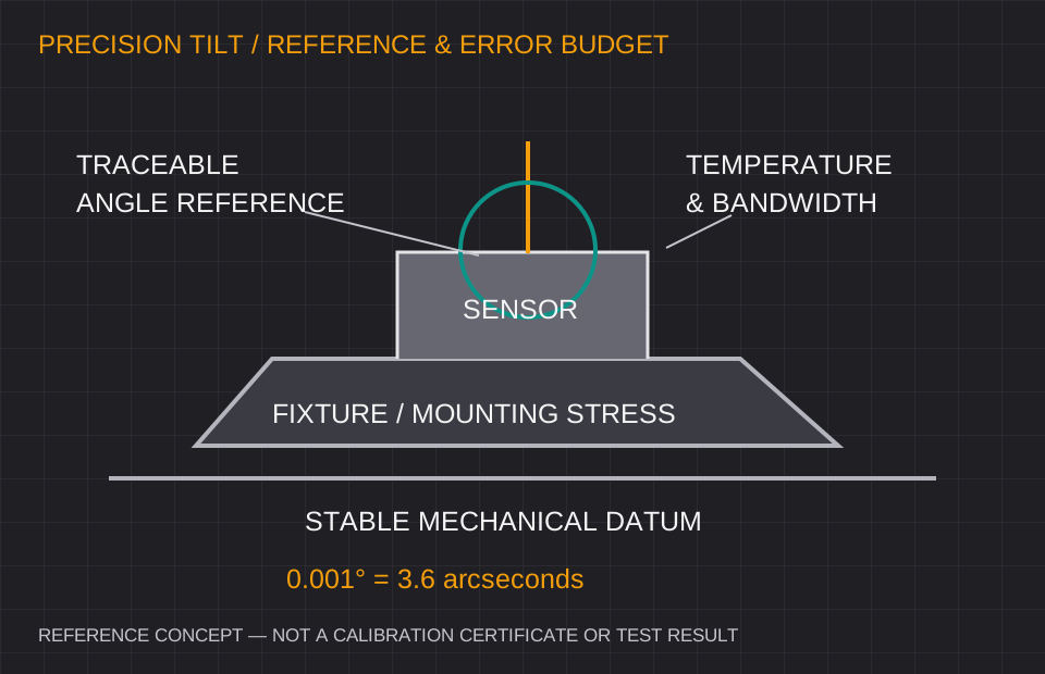
Precision tilt measurement concept connecting a stable datum, mounting fixture, sensor and traceable angular reference
Error-budget concept, not a calibration certificate or measured performance chart. Open diagram ↗

Define your operating window

ICS-PREC: range, interface and error budget.

Axes & range
Small-range options ±1°, ±3°, ±5°, ±10°, ±15° and ±30°
Performance request
Requested resolution 0.0005°–0.001°; accuracy target ±0.002°–±0.005°; thermal coefficient target <0.0005°/°C. Confirm by released configuration.
Output interface
Request analog or digital interface and the matching sampling / filtering specification.
Installation environment
Temperature stability, mounting strain and warm-up dominate small-angle measurements.

Values are selection targets for quotation. Model-specific test conditions, calibration and released specifications govern acceptance.

Where this configuration fits

Radar and satellite antenna leveling, rail geometry, wind-tower tilt and precision machine alignment.

Before approving the sample

  • 0.001° = 3.6 arcseconds; 0.0005° = 1.8 arcseconds. Neither is sub-arcsecond.
  • Resolution is not absolute accuracy; request calibration uncertainty and bandwidth.
  • Confirm actual sensing technology; servo-equivalent positioning is not proof of force-balanced construction.

Comparing an existing inclinometer?

Reference families: Jewell LSO / LCF / DX, Sherborne / Schaevitz servo inclinometers and Wyler Zerotronic. These are evaluation starting points. Confirm exact model, mechanical drawing, electrical behavior and acceptance test before claiming interchangeability.

Review the replacement checklist →

ICS-PREC / Installation & integration decisions

0.001° resolution needs a complete measurement error budget.

Small output increments are useful only when the datum, fixture, temperature and reference method support the measurement. At 0.001°, the displayed increment is 3.6 arcseconds; at 0.0005°, it is 1.8 arcseconds. Neither increment establishes absolute accuracy.

Separate the output step from uncertainty

A precision request should identify the required range, absolute error, repeatability, noise bandwidth and temperature window independently. Averaging can make a display look stable while concealing slow response or drift. State the observation period and allowable settling time.

  • Define the angle reference, comparison method and required uncertainty statement.
  • Specify zero offset, nonlinearity, cross-axis effects and temperature sensitivity separately.
  • Request actual sensing principle and signal transfer function for the matched model.

Mounting fixture and thermal equilibrium

Surface flatness, mounting stress and a shifting datum can dominate micro-tilt readings. A general adjustment plate is an installation option for review, not an assurance of metrology-grade stability. Agree fixture material, contact geometry, torque and thermal stabilization for the actual setup.

  • Define where the reference plane lives and how it is reproduced.
  • Record warm-up, temperature gradient and mounting torque in the procedure.
  • Review a purpose-suited fine-leveling fixture before quoting the accessory package.

Antenna, rail and tower measurements

Antenna leveling, rail geometry and wind-tower micro-tilt involve different reference frames and environmental loads. A gravity-referenced tilt measurement also does not supply an absolute north reference. Define the measured quantity and its acceptance method before selecting a precision range.

  • Separate inclination from heading or north-finding requirements.
  • For long-term monitoring, define reference stability and drift-check intervals.
  • Request the selected analog or digital interface with its bandwidth and calibration scope.

Precision measurement review checklist

Budget termQuestion for the reviewEvidence to request
ResolutionWhat is the smallest reported increment?Output format and scaling
Absolute errorOver which range, temperature and mounting condition?Model error limits and calibration method
Noise / settlingAt what bandwidth and averaging time?Recorded test conditions
Thermal driftZero and sensitivity across which window?Temperature-dependent measurements
Mounting datumHow stable is the installed reference?Fixture and reference procedure
Is a factory inspection sheet the same as an accredited calibration report?

Ask for the document type, reference chain, uncertainty, conditions and the issuing organization’s applicable scope. The required evidence depends on the project’s measurement and quality requirements.

Can a fine output step compensate for a moving mounting base?

No. Define base stability and mechanical reference repeatability as part of the complete measurement. Output resolution cannot remove a shifting installation datum.

ICS-PREC / Engineering integration package

Request the files your design review needs.

Choose the document and send your range, interface and mounting requirements. We review the matched configuration and confirm which released files can be supplied.

Static MEMS or gyro-compensated dynamic?

Match the motion before the resolution.

Static or slow-moving equipment

Start with ICS-DUAL for solar trackers, platform leveling and stationary machinery. For micro-tilt monitoring, review ICS-PREC or ICS-GEO and the temperature error budget.

Acceleration, vibration or sudden stops

Review ICS-DYN for moving excavator booms, loader buckets and vehicles. Sensor fusion reduces apparent tilt from motion; validate dynamic error, bandwidth and recovery against your duty cycle.

Inclinometer vs. accelerometer: understand the difference →

Replacing an existing unit? Start with the interface checklist →

Planning 20+, 100+ or 1,000+ units? Solar trackers, scissor lifts & construction equipment OEM.Request volume pricing & OEM interface settings ↗

ICS-PREC / project inputs

Configure your ICS-PREC inquiry and integration scope.

Send the installation requirements below. Request 3D CAD, pinout and the calibration scope for the configuration under review.

Industrial sensor inquiry form

Interface and mounting fixture are reviewed for the requested precision. No in-cab display is added by default.

Range, environment & mounting (optional)

Describe the required conditions. These values are your application targets, not a confirmed product specification.

Engineering documents & project package (optional)
Files requested for configuration review

Package scope and document availability are confirmed for the matched configuration. A package request has no separate price; select the display accessory once if it is needed.

Installation accessories (optional)

Selected accessory planning allowance: USD 0. Indicative add-ons; the formal quote confirms compatibility, quantity, freight, tax and lead time.

Your request goes to [email protected]. CAD, performance and delivery are reviewed after feasibility checks for the requested configuration.