ICS-DSP / Sensor + readout

Inclinometer Sensors with Digital Angle Display & Alarm Kits

Pair pitch / roll sensing with a readable in-cab display and configurable alarms. Agree the sensor interface, alarm behavior and installation wiring as one kit.

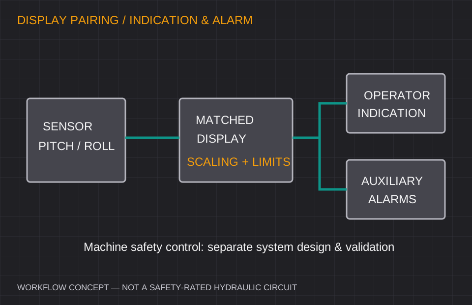
Concept diagram from a tilt sensor through a matched display to operator indication and auxiliary alarm outputs, with machine safety reviewed separately
Indication and alarm concept; it does not define a safety-rated hydraulic circuit. Open diagram ↗

Define your operating window

ICS-DSP: range, interface and error budget.

Axes & range
X/Y pitch and roll display; panel or bracket mounting options.
Performance request
Requested 12–24 V DC supply, audible alarm and two relay outputs; confirm ratings and fault behavior.
Output interface
Matched RS485 or analog sensor input — not every display supports every protocol.
Installation environment
Check display sunlight readability, cab temperature and connector protection separately.

Values are selection targets for quotation. Model-specific test conditions, calibration and released specifications govern acceptance.

Where this configuration fits

Crane and forklift indication, dump-truck tilt monitoring and platform leveling displays.

Before approving the sample

  • A relay output is not certified rollover protection or a safety controller.
  • Hydraulic shutoff needs machine-level risk assessment, fault handling and validation.
  • Confirm pinout, scaling, relay rating, hysteresis and power-loss state.

Comparing an existing inclinometer?

Reference families: Rieker digital tilt indicators and industrial angle readout systems. These are evaluation starting points. Confirm exact model, mechanical drawing, electrical behavior and acceptance test before claiming interchangeability.

Review the replacement checklist →

ICS-DSP / Installation & integration decisions

Pair the sensor, readout and alarm behavior in one brief.

A useful in-cab display request specifies both the sensor signal and what the operator should see. Include the measurement range, X/Y sign convention, scale, supply, warning thresholds and the equipment’s intended fault response.

Display input and angle scaling

For analog input, the display must apply the same endpoints as the sensor and provide the required number of channels. For a digital input, register mapping, units, signed values and update timing must agree. Request a pairing guide for the matched configuration.

  • Confirm sensor type, input interface and displayed X/Y units.
  • Describe panel or bracket mounting and connector access.
  • Specify sunlight readability, temperature and operator viewing distance.

Threshold and window modes: define the logic

A threshold compares a value with a boundary; a window compares it with an allowed interval. If supported by the selected controller, warning stages, audible indication and relay behavior need explicit setpoints, hysteresis and reset conditions. The rows below are review topics, not a declaration of available modes.

  • Specify high/low limits, delay, hysteresis and latching requirements.
  • Record relay contact ratings, inductive loads and required power-loss state.
  • Define sensor-disconnection, stale-data and out-of-range indications.

General alarm versus a machine safety function

A display relay can support operator indication or auxiliary signaling. Any safety-related machine action needs a system design with the required diagnostic coverage, failure response and validation. Request the relevant control-system evidence rather than assuming a readout alone establishes rollover protection.

  • Keep operator warnings and safety control requirements distinct.
  • Include the equipment control architecture and commissioning method.
  • Review the sensor, harness and display as one configuration; an extra display is not preselected.

Alarm behaviors to confirm for the selected controller

Review topicWhat the buyer definesWhat the review confirms
High / low thresholdBoundary and reset pointsSupported comparator and hysteresis behavior
Allowed angle windowLower/upper limit and X/Y treatmentSupported window and logic mapping
Audible / visual warningOperator warning stages and acknowledgementSelected display capabilities
Relay outputContact load and required default stateRatings, timing and loss-of-power behavior
Signal faultDisconnected or stale sensor dataDiagnostic indication and output state
Is the additional +$165 display selected on this page?

No. This is already a display-configuration request. An extra display is excluded from the accessory choices; the formal quote defines the sensor, display, harness and other included items.

Can an alarm relay directly establish a certified rollover interlock?

No. Define and validate the machine’s safety control function separately, including sensor faults, power loss, contact behavior and the applicable system requirements.

ICS-DSP / Engineering integration package

Request the files your design review needs.

Choose the document and send your range, interface and mounting requirements. We review the matched configuration and confirm which released files can be supplied.

Static MEMS or gyro-compensated dynamic?

Match the motion before the resolution.

Static or slow-moving equipment

Start with ICS-DUAL for solar trackers, platform leveling and stationary machinery. For micro-tilt monitoring, review ICS-PREC or ICS-GEO and the temperature error budget.

Acceleration, vibration or sudden stops

Review ICS-DYN for moving excavator booms, loader buckets and vehicles. Sensor fusion reduces apparent tilt from motion; validate dynamic error, bandwidth and recovery against your duty cycle.

Inclinometer vs. accelerometer: understand the difference →

Replacing an existing unit? Start with the interface checklist →

Planning 20+, 100+ or 1,000+ units? Solar trackers, scissor lifts & construction equipment OEM.Request volume pricing & OEM interface settings ↗

ICS-DSP / project inputs

Configure your ICS-DSP inquiry and integration scope.

Send the installation requirements below. Request 3D CAD, pinout and the calibration scope for the configuration under review.

Industrial sensor inquiry form

This request already concerns a display configuration. A second display is not added as an accessory; sensor pairing is reviewed as one package.

Range, environment & mounting (optional)

Describe the required conditions. These values are your application targets, not a confirmed product specification.

Engineering documents & project package (optional)
Files requested for configuration review

Package scope and document availability are confirmed for the matched configuration. A package request has no separate price; select the display accessory once if it is needed.

Installation accessories (optional)

Selected accessory planning allowance: USD 0. Indicative add-ons; the formal quote confirms compatibility, quantity, freight, tax and lead time.

Your request goes to [email protected]. CAD, performance and delivery are reviewed after feasibility checks for the requested configuration.